SPM Operating Principles

SPM methods are techniques that is generally covered in all techniques of surface science text books so only brief a summary of the techniques is given here.

Scanning probe microscopes provide very high resolution images of various sample properties. The atomic force microscope is one of about two dozen types of scanning probe microscopes. All of these microscopes work by measuring a local property - such as height, optical absorption, or magnetism - with a probe or "tip" placed very close to the sample. The small probe-sample separation (generally of the order of the instrument's resolution) makes it possible to take many measurements over a small area. To acquire an image the microscope raster-scans the probe over the sample while measuring the local property in question. The resulting image is analogous to an image on a television screen; both consist of many rows or lines of information placed one above the other. Unlike traditional microscopes, scanning probe systems do not use lenses, so their resolution is limited by the size of the probe rather than diffraction effects.

The atomic force microscope measures topography with a microscopic force probe.

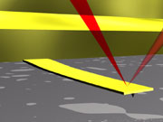
It operates by measuring attractive or repulsive forces between a tip and the sample. In repulsive "contact" mode mode, the instrument lightly touches a tip at the end of a leaf spring or "cantilever" to the sample. As a raster-scan drags the tip over the sample, some sort of detection apparatus measures the vertical deflection of the cantilever, which indicates the local sample height. Hence, AFM resembles the record player as well as the stylus profilometer and unlike electron microscopes, can generally image samples in air and under liquids.

Thus, in contact mode the AFM measures hard-sphere repulsion forces between the tip and sample.

In Tapping mode the "cantilever" is made to vibrate at close to its natural frequency and the proximity of the surface is determined by the damping of this oscillation. This eliminates lateral shear forces on the tip and reduces the force normal to the tip and the surface which can damage soft samples

In noncontact mode, the AFM derives topographic images from measurements of attractive forces; the tip does not touch the sample, however it does not allow the imaging of samples under water.

AFMs can generally measure the vertical deflection of the cantilever with picometer resolution. The "optical lever" method of Laser beam deflection offers a convenient and sufficiently sensitive method of measuring cantilever deflection. This device that achieves resolution comparable to an interferometer while remaining inexpensive and easy to use.

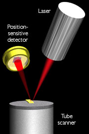
The optical lever operates by reflecting a laser beam off the cantilever. Angular deflection of the cantilever causes double the angular deflection of the laser beam. The reflected laser beam strikes a position-sensitive photodetector consisting of two side-by-side photodiodes. The difference between the two photodiode signals indicates the position of the laser spot on the detector and thus the angular deflection of the cantilever. Because the cantilever-to-detector distance generally measures thousands of times the length of the cantilever, the optical lever greatly magnifies (~2000-fold) motions of the tip.


AFM Probes

Most users purchase AFM cantilevers with their attached tips from commercial vendors, who manufacture the tips with a variety of microlithographic techniques.

A high flexibility stylus exerts lower downward forces on the sample, resulting in less distortion and damage while scanning. For this reason AFM cantilevers generally have spring constants of about 0.1 N/m.
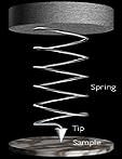
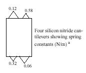
Schematic illustration of the meaning of spring constant as applied to AFM cantilevers. Visualizing the cantilever as a coil spring, its spring constant k directly affects the downward force exerted on the sample.
To enable rapid imaging the AFM cantilever should have a high resonant frequency. The equation for the resonant frequency of a spring:


shows that a cantilever can have both low spring constant and high resonant frequency if it has a small mass. Therefore AFM cantilevers tend to be very small. Commercial vendors manufacture almost all AFM cantilevers by microlithography processes similar to those used to make computer chips. The
Veeco contact mode cantilever shown in the electron micrograph below measures 100 µm in length.

A close enough inspection of any AFM tip reveals that it is rounded off. Therefore force microscopists generally evaluate tips by determining their nominal tip radius, In combination with tip-sample interaction effects, this end radius generally limits the resolution of AFM.

Two standard types of probes are available from the SAF (many others are also available for specific experiments please contact the SAF for details):

Contact mode probes consist of silicon nitride with a thin coating of gold to act as a mirror for the laser beam. These have a nominal tip radius between 20 and 60 nm, the pyramidal tip is shown in the first electron micrograph below. They have four V-Shaped cantilevers (two 100 µm in length and two 100 µm in length) per substrate, as shown schematically below, with approximate spring constants 0.58, 0.32, 0.12 and 0.06 N/m. An electron micrograph of the 0.32 cantilever is also shown.


Tapping mode probes consist of an etched single crystal of silicon. These have a nominal tip radius between 5 and 10 nm, the tip is shown in the first electron micrograph below. They have just 1 single beam cantilevers (125 µm in length) per substrate, with a spring constant between 20 and 100 N/m. An electron micrograph of the inverted cantilever is also shown.

Sample Manipulation

Tube piezoceramics are used to position and scan the sample with high resolution. Piezoelectric ceramics are a class of materials that expand or contract when a voltage is applied across them, conversely, create a voltage across the material when forced to expand or contract. Piezoceramics make it possible to create three-dimensional positioning devices of very high precision. Most scanned-probe microscopes use tube-shaped piezoceramics because they combine a simple one-piece construction with high stability and large scan range. Four electrodes cover the outer surface of the tube, while a single electrode covers the inner surface. Application of voltages to one or more of the electrodes causes the tube to bend or stretch, and hence the sample can be moved in all three dimensions. For example by applying a voltage to one of the four outer quadrants, relative to the center electrode, causes that quadrant to expand and the scanner to tilt away from it (XY movement). A corresponding negative voltage applied to the opposite quadrant, relative to the center electrode, doubles the XY range while preventing vertical motion. Applying a voltage to the inner electrode, relative to all the outer four electrodes, causes the entire tube to expand or contract (Z movement).

Feedback

The presence of a feedback loop is one of the subtler differences between AFMs and older stylus-based instruments such as record players and stylus profilometers. The AFM not only measures the force on the sample but also regulates it, allowing acquisition of images at low forces.

The feedback loop consists of the tube scanner, sample, cantilever and optical lever, and a feedback circuit. It is the compensation network (a computer program) that monitors the cantilever deflection and attempts to keep it constant by varying the voltage applied to the scanner and hence adjusts the height of the sample. Hence an AFM can measure sample topography in two ways: by recording the feedback output ("Z") or the cantilever deflection ("C"). The sum of these two signals always yields the actual topography, but given a well-adjusted feedback loop, the error signal should be negligible.

One point of interest: the faster the feedback loop can correct deviations of the cantilever deflection, the faster the AFM can acquire images; therefore, a well-constructed feedback loop is essential to microscope performance. AFM feedback loops tend to have a bandwidth of about 10 kHz, resulting in image acquisition times of about one minute.

Force curves can be obtained by switching off the feedback loop and varying the tip to sample distance and observing the deflection "C". When imaging in air, a layer of water condensation and other contamination covers both the tip and sample, forming a meniscus that pulls the two together. "Force curves" showing cantilever deflection as the scanner lowers the sample reveal the attractive force; the cantilever has to exert an upward force to pull the tip free of the meniscus. This force equals the attractive force of the meniscus, usually 10-100 nN. The high surface tension of water makes this a major factor in obtaining force curves using an AFM and hence Force microscopists often eliminate the meniscus by completely immersing both tip and sample in water.


Back to the instruments page